Schematics
Front panel
The front panel contains the power button, power led and the status led. The power led is always on when the Teleport is powered up, and is therefore the first indicator to see whether the Teleport is powered up.

Back panel
The back panel contains the ethernet connectors, ETH1 and ETH2, the DC connector, and the main serial connector.

The pin functions for the main serial connector are shown in the following table.
| pin | RS-485 function |
|---|---|
| 1 | D- (A) |
| 2 | D+ (B) |
| 3 | GND |
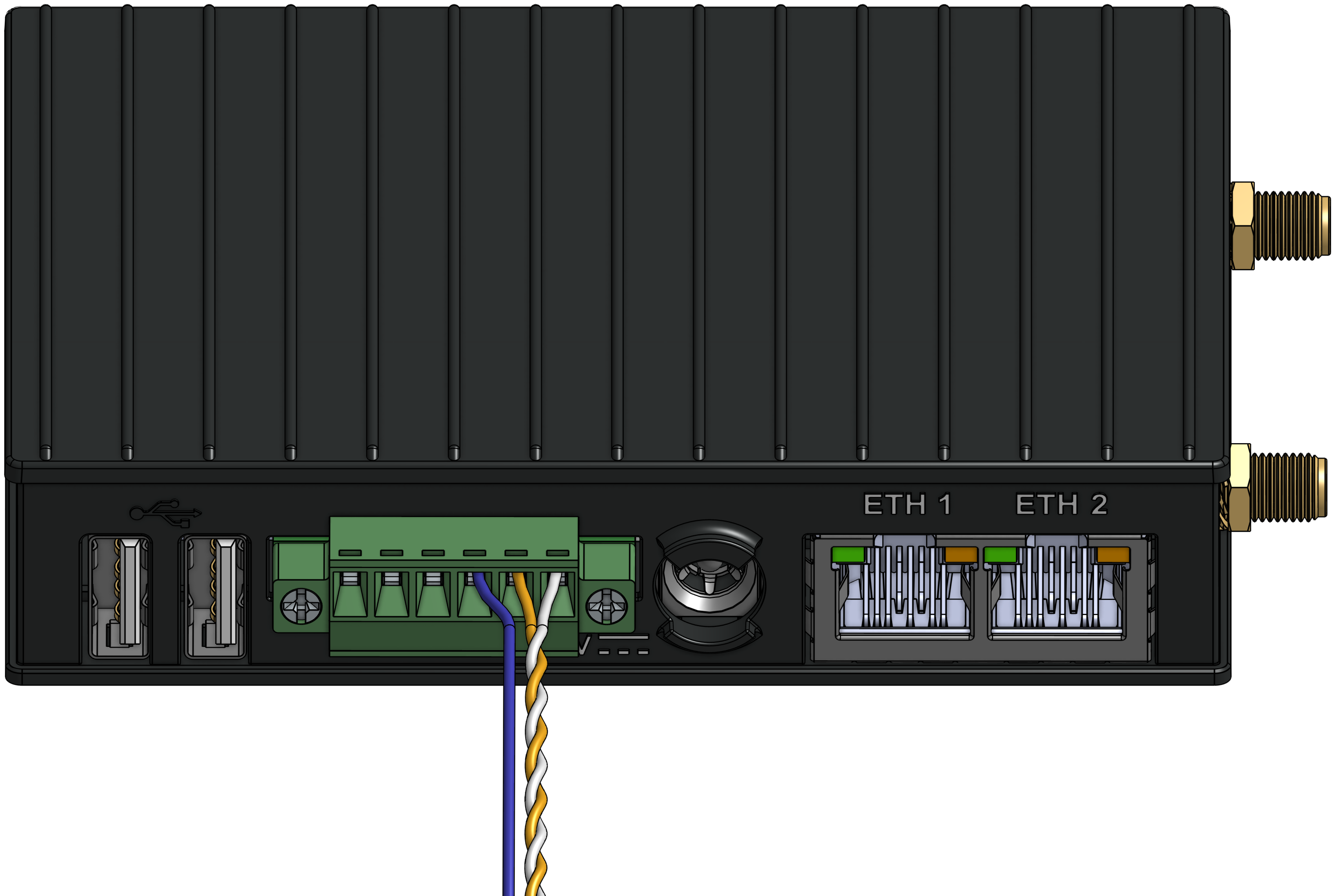
The following image shows an example of the connected RS-485 cable to this connector where D- is white, D+ is orange, and GND is blue.

Side panel
The side panel contains the antenna used for the cellular connection, ANT4, and optionally the add-on connector. The add-on connector is only present when the add-ons are needed, e.g. when connecting to multiple RS-485 lines. It can provide connections for up to two add-ons, A and B.

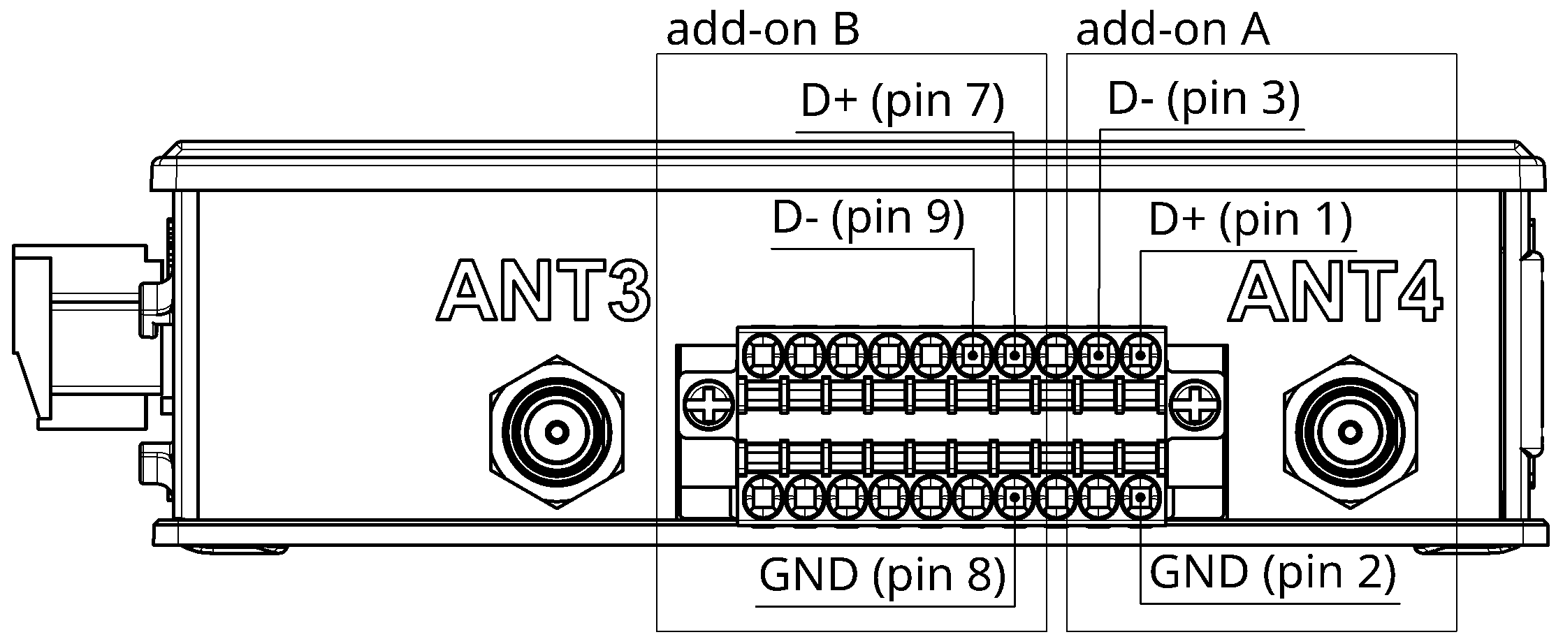
The pin functions for the add-on connector are shown in the following table.
| pin | add-on | RS-485 function |
|---|---|---|
| 1 | add-on A | D+ (B) |
| 2 | add-on A | GND |
| 3 | add-on A | D- (A) |
| 7 | add-on B | D+ (B) |
| 8 | add-on B | GND |
| 9 | add-on B | D- (A) |
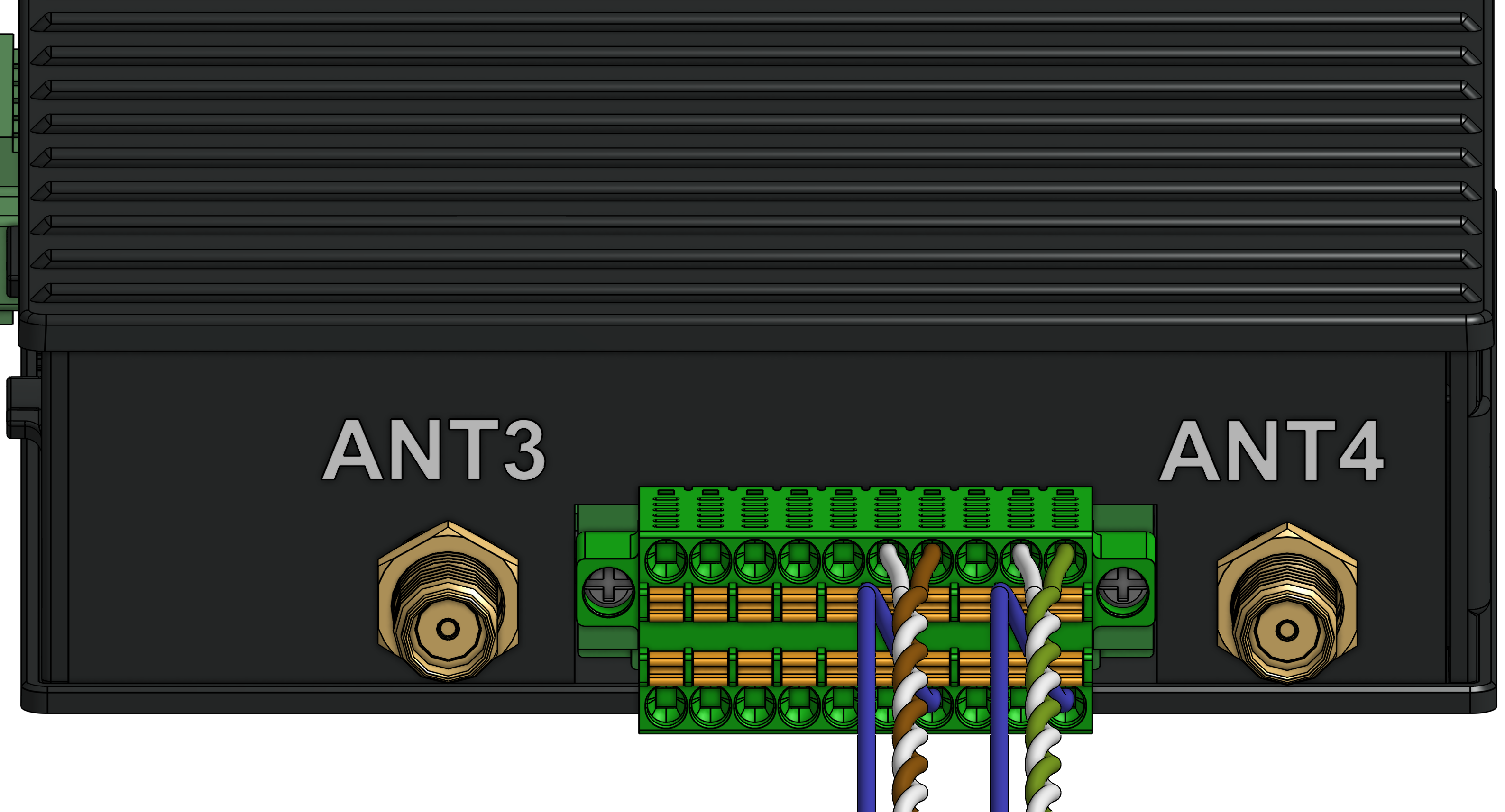
The following image shows an example of the connected RS-485 cables to this connector.
- For add-on A,
D-is the white paired with the green,D+is green, andGNDis the green next to the green/white pair. - For add-on B,
D-is the white paired with the brown,D+is brown, andGNDis the brown next to the brown/white pair.

RS-485
The RS-485 D- signal has A as an alternative name and the D+ signal has B as an alternative name. Manufacturers tend to mix up the A and B naming though, which is why they’re here referred to as D- and D+ to prevent any ambiguity.