

Automatic failover rack
Introduction
For battery energy storage systems (BESS) and other critical sites that require high availability, the Teleport is available as a pre-assembled 19” rack-mount unit with built-in automatic failover. The unit combines two Teleports, two DC power supplies and a failover relay in a single chassis, so that read-out and control of your assets continue uninterrupted if a single Teleport or power supply fails.
The package is sent fully assembled; it only needs to be placed in the server rack, connected to power and connected to the asset(s). It is the high-availability version of the Teleport for BESS package.
What’s included
The unit includes:
- Two Teleports — a primary (active) and a backup (standby)
- Two DC power supplies, one for each Teleport
- Two C14 power cords (male)
- A relay that cuts power to the primary Teleport when the backup takes over
- 19” rack-mount chassis (3U)
- Internal wiring and U/UTP cat 5e network cabling
How automatic failover works
Both Teleports are always powered and are connected to the asset(s), but only the active Teleport reads from and controls the asset(s). Under normal operation the primary Teleport is active and the backup Teleport runs in standby.
The primary Teleport is powered through the normally-closed contact of the failover relay, which is controlled by the backup Teleport. The backup Teleport continuously monitors the primary over the internal network with a TCP heartbeat. As long as the primary keeps responding, the backup stays in standby.
If the primary stops responding for about 10 seconds, the backup opens the relay, cutting power to the primary, and takes over reading and controlling the asset(s), without manual intervention. Once the primary Teleport is available again, control can be handed back to it.
Both Teleports maintain their own connection to the Teleport cloud, so Withthegrid can distinguish primary and backup device communication. If a Teleport fails, Withthegrid informs the customer.
Wiring diagram
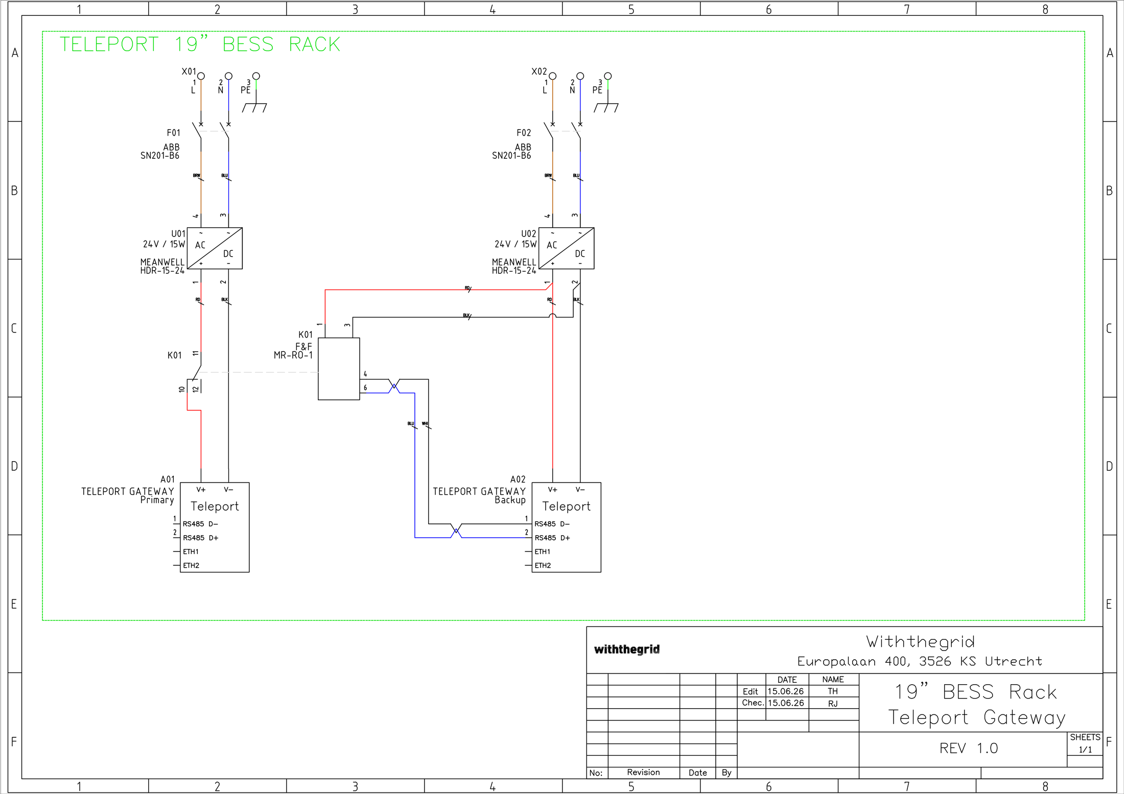
The wiring diagram below shows the two AC inputs (X01, X02), each protected by an ABB SN201-B6 circuit breaker and feeding a Mean Well HDR-15-24 24 V power supply, the primary and backup Teleport (A01, A02), and the F&F MR-RO-1 relay (K01) whose normally-closed contact powers the primary Teleport. The RS-485 lines are wired to both Teleports in parallel.
Installation guide
-
Place the unit in the server rack and fix it to the rack rails. The unit requires 3U of rack space.
-
Connect both power supplies to a power source using the two supplied C14 power cords. For maximum availability, supply each power supply from an independent (redundant) feed, for example separate circuits or a UPS-backed outlet.
-
Connect the asset(s) and the network as instructed in the Installation guide. Both Teleports are wired to the asset(s) in parallel; the active Teleport handles the communication.
-
Power up the unit. Each Teleport starts up automatically and its power led turns on, as described in Power it up.
Specifications
| Dimensions | 19” 3U |
| Teleports | 2x (primary + backup) |
| Power supplies | 2x Mean Well HDR-15-24 (100 VAC to 240 VAC input, 24 VDC / 15 W output), each fed by a C14 power cord |
| Failover relay | F&F MR-RO-1 (automatic) |